File:Gage1912 fig01.jpg
Original file (1,000 × 438 pixels, file size: 49 KB, MIME type: image/jpeg)
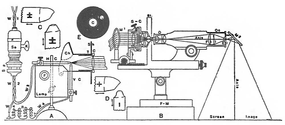
Fig. 1. Diagram of the Microscope for drawing
Online Editor - Edinger projection apparatus was developed in 1907 by Dr. L. Edinger (director of the Neurologic Institute at Frankfurt on Main). He replaced his drawing and photographing apparatus using either oil or gas light, with one using a small arc lamp. This small arc lamp was worked out and perfected by the optical works of Leitz at Wetzlar. (See Anson BJ. The early development of the membranous labyrinth in mammalian embryos, with special reference to the endolymphatic duct and the utriculo—endolymphatic duct. (1934) Anat. Rec. 59: 15-25.)
The Arc Lamp with small right angled carbons, the Wiring, the Rheostat and the connections with the house lighting system.
The Arc Lamp with small right angled carbons, the Wiring, the Rheostat and the connections with the house lighting system.
A. The small arc lamp with the condenser (C) giving parallel rays, the vertical (V-C) and the horizontal (H-C) carbons; F the feeding mechanism, and the wires (W3, direct from the line, W4 through the rheostat). The rheostat (R) is in one wire. The separable plug (Sp) is connected below with the cable (W2) and above with the lamp socket (So) with its key switch, (K). Still above is the incandescent lamp cable (W1) connecting the lamp socket with the house current.
B. The Microscope in section showing the beam of parallel rays from the lamp condenser entering the substage condenser (S-C) directly (as in fig. 14) or reflected in by the mirror (311) as in fig. 2, 3, 12, 15); St. Stage of the microscope; O objective, Fl, I, El, the field lens, the real image and the eye lens of the ocular (Oc); M2 the prism or 45 degree mirror for reflecting the image forming rays down on the drawing paper.
C. Cored carbons of equal size for alternating current.
D. Carbons of the correct relative size for direct current.
E. Face view of the disc on the end of the lamp condenser tube showing the condenser (C) and the spot of light (I) reflected back from the substage condenser.
Reference
Gage SH. Recent Developments in Drawing by the Aid of Projection Apparatus, Used on the House Lighting System. (1912) Transactions of the American Microscopical Society. 31(3): 177-197.
Cite this page: Hill, M.A. (2024, April 26) Embryology Gage1912 fig01.jpg. Retrieved from https://embryology.med.unsw.edu.au/embryology/index.php/File:Gage1912_fig01.jpg
- © Dr Mark Hill 2024, UNSW Embryology ISBN: 978 0 7334 2609 4 - UNSW CRICOS Provider Code No. 00098G
File history
Click on a date/time to view the file as it appeared at that time.
| Date/Time | Thumbnail | Dimensions | User | Comment | |
|---|---|---|---|---|---|
| current | 15:45, 4 October 2017 | | 1,000 × 438 (49 KB) | Z8600021 (talk | contribs) | |
| 15:39, 4 October 2017 | 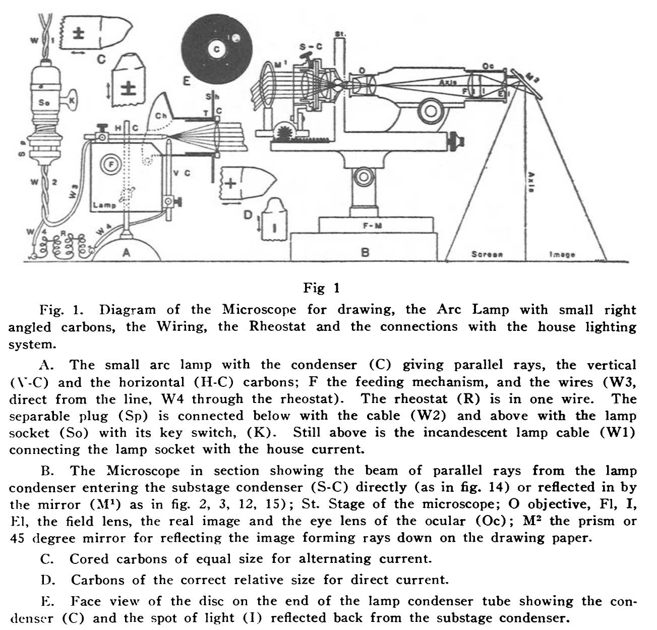 | 1,303 × 1,249 (209 KB) | Z8600021 (talk | contribs) | {{Ref-Gage1912}} |
You cannot overwrite this file.