File:ZLinear Array Transducer.jpg
Original file (1,183 × 1,595 pixels, file size: 221 KB, MIME type: image/jpeg)
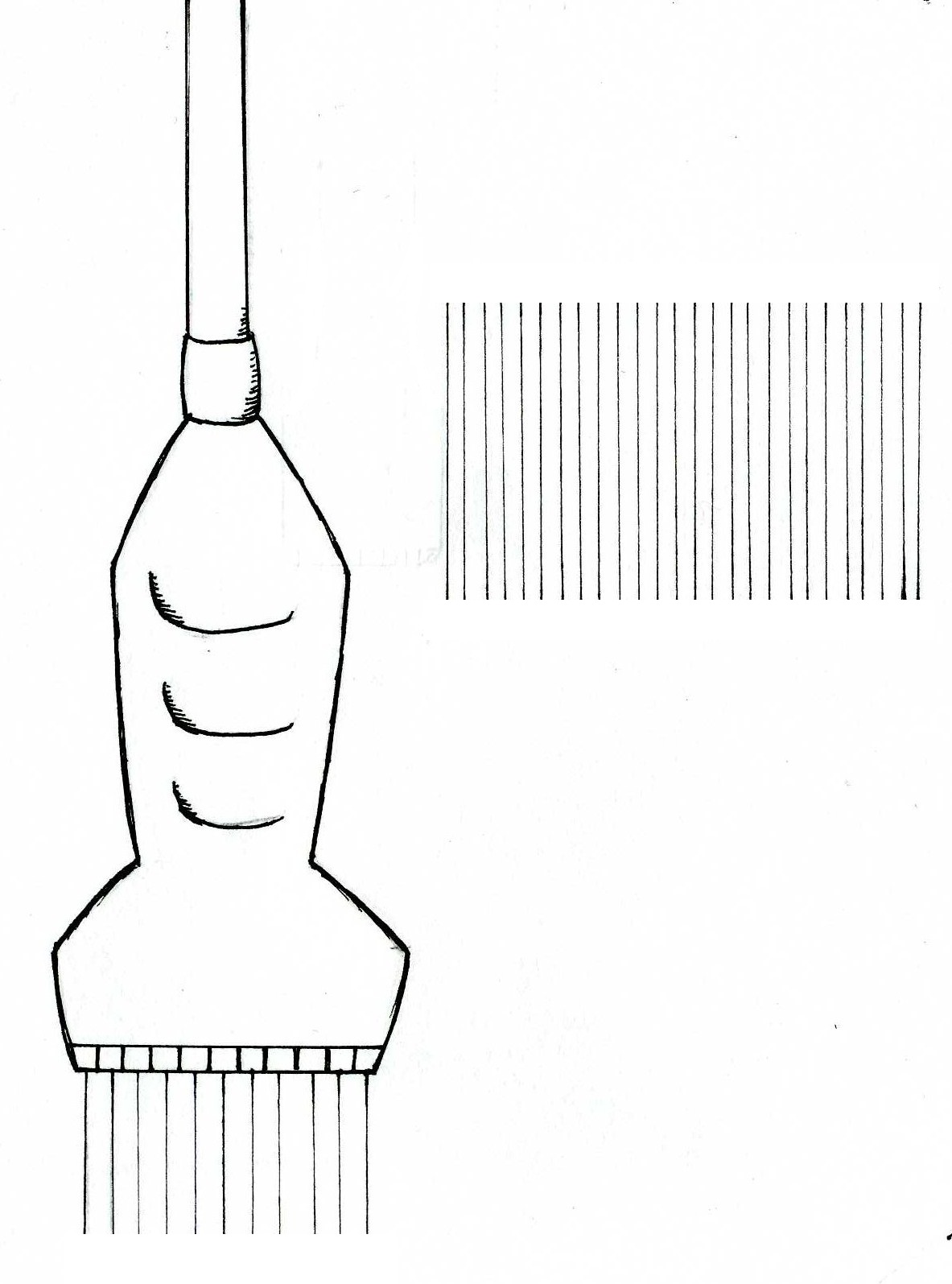
Explanation of Diagram
This diagram shows a linear array transducer emitting ultrasound pulses on the left, and the shape of the scan it produces on the right.
The illustration of a linear transducer on the left demonstrates the placement of piezoelectric elements in a linear array transducer – side by side, with pulses being emitted vertically and in parallel lines. A complete name for this transducer is the linear sequenced array transducer (‘sequenced’ meaning that it automatically emits pulses in sequence to form a real-time image of the patient).
The illustration on the right indicates the shape of the image produced, termed a linear or rectangular scan.
Image Copyright Information
Illustration by z3252833.
Beginning six months after publication, I, z3252833, grant the public the non-exclusive right to copy, distribute, or display the Work under a Creative Commons Attribution-Noncommercial-Share Alike 3.0 Unported license, as described at http://creativecommons.org/licenses/by-nc-sa/3.0/ and http://creativecommons.org/licenses/by-nc-sa/3.0/legalcode.
References
Kremkali, F.W. (2006) Diagnostic Ultrasound Principles and Instruments (7th ed.) St Louis: Saunders Elsevier. pp 66-67
File history
Yi efo/eka'e gwa ebo wo le nyangagi wuncin ye kamina wunga tinya nan
| Gwalagizhi | Nyangagi | Dimensions | User | Comment | |
|---|---|---|---|---|---|
| current | 17:49, 12 September 2010 | | 1,183 × 1,595 (221 KB) | Z3252833 (talk | contribs) | ===Explanation of Diagram=== This diagram shows a linear array transducer emitting ultrasound pulses on the left, and the shape of the scan it produces on the right. The illustration of a linear transducer on the left demonstrates the placement of piez |
You cannot overwrite this file.
File usage
The following page uses this file: