File:Macklin-plate03.jpg: Difference between revisions
(==Plate 3. The skull of a human fetus of 43 millimeters greatest length== By Charles C. Macklin. (5 plates containing 47 figures) All drawings were made by Mr. James F. Didusch according to geometric projection. With the exception of figure 7, which was) |
No edit summary |
||
| Line 32: | Line 32: | ||
Fig 25. View of same mass of cartilage shown in figure 24, but seen from below. The lateral semicircular canal is conspicuous to the left, passing above into an enlargement for the ampulla of this canal and for the utriculus, with the beginning of the superior canal above. Below, the lateral canal passes medially into an erdargement for the | Fig 25. View of same mass of cartilage shown in figure 24, but seen from below. The lateral semicircular canal is conspicuous to the left, passing above into an enlargement for the ampulla of this canal and for the utriculus, with the beginning of the superior canal above. Below, the lateral canal passes medially into an erdargement for the | ||
inferior extremity of the posterior canal and for the crus commune. Model 15. XlO. Views of the angular mass from other aspects are seen in other figures, as from without in figures 20, 5, 6, and from within infigure 15. | inferior extremity of the posterior canal and for the crus commune. Model 15. XlO. Views of the angular mass from other aspects are seen in other figures, as from without in figures 20, 5, 6, and from within infigure 15. | ||
{{Glossary}} | |||
{{Footer}} | |||
[[Category:Human]] [[Category:Hearing]] | |||
Revision as of 14:51, 16 April 2011
Plate 3. The skull of a human fetus of 43 millimeters greatest length
By Charles C. Macklin. (5 plates containing 47 figures)
All drawings were made by Mr. James F. Didusch according to geometric projection. With the exception of figure 7, which was made from a profile reconstruction, all figures were drawn from the original plaster-of-paris models made from human fetus No. 886 of the collection of the Carnegie Laboratory of Embryology. The number of the model from which each figure was drawn is given, together with the magnification.
Note - the magnifications refer to the original print versions, not the online images.
Fig. 15. Interior of right otic capsule from within and above. The inner wall of the capsule has been cut away to show the lateral wall of the cavity. Figure 21 shows this cavity modeled as a solid. The superior and posterior semicircular canals are shown, with the entrances to the lateral canal. A good view is afforded of the spiral septum in the wall of the cochlear space. The membrane fiUing in the vestibular window is indicated. Other features are the
medial end of the tuba auditiva with its entrance into the pharynx, the alar process of the temporal wing of the sphenoid, the aUcochlear commissure, the internal carotid artery, and views of the fifth and seventh cranial nerves. Model 14. XlO.
Fig. 16. Right otic capsule and associated structures seen from right side, front, and a little below. The suprafacial commissure has been removed. The facial nerve is shown in its relation to the otic capsule and styloid process, with its off-shoots, the chorda tympani and the great superficial petrosal nerves, the latter arising from the geniculate gangUon. The tip of the long crus of the incus appears in relation to the chorda tympani. A prominent object is the tympanic cavity fundament, of which the lateral surface is shown, presenting an impression at the site of the future tympanic membrane. The auditory tube is shown in its full extent. The immense semilunar ganglion with its root and branches, the internal carotidartery, and the processus alaris of the temporal wing of the sphenoid are seen. Model 14. XlO.
Fig. 17. Right otic capsule, medial surface, frank view, showing connections with adjoining cartilages and openings toward the cranial cavity. Model 5. XlO.
Fig. IS. The space within the right otic capsule seen from within, modeled as a solid; the surface presented fits into the cavity shown in figure 23. Openings toward the cranial cavity are shown. Note the large volume of this cavity in comparison with that of the membranous labyrinth wliich fills it (fig. 19). Compare also figures 21 and 22 in this respect. Model 6. XlO.
Fig. 19. Membranous labyrinth of right otic capsule contained within the space shown in figure 18. Figures 17, 18, and 19 were all drawn from approximately the same point of view, so that an accurate idea may be gained of the space contained within the otic capsule and the membranous labyrinth within that. Model 7. XlO.
Fig. 20. Right otic capsule, lateral surface, frank view, with openings looking outward. The attachments of the cartilage of Reichert and of the short process of the incus are seen. Model 5. XlO.
Fig. 21. The space within the right otic capsule, seen from without, modeled as a sohd; the openings are indicated. Model 6. XlO.
Fig. 22. Membranous labyrinth of right otic capsule contained within the space shown in figure 21. Figures 20, 21, and 22 were all drawn from approximately the same point of view. Model 7. XlO.
Fig. 23. Medial wall of right otic capsule, seen from without, the lateral wall having been cut away. The cutting of the capsular wall was not done in quite the same way as in the model shown in figure 15, so that the cut edges do not fit together exactly. The inner wall of the space is seen with the endolymphatic and internal acoustic foramina. Model 26. XlO.
Fig. 24. View from front of mass of cartilage (massa angularis) partially inclosed by the semi- circular canals of the right otic capsule. Above is seen the superior canal leading into the space for its ampulla and, farther downward and to the right, into that for the utriculus. To the left is the space for the ampulla of the lateral canal and, farther back, the lateral semicircular canal appears. Model 15. XlO.
Fig 25. View of same mass of cartilage shown in figure 24, but seen from below. The lateral semicircular canal is conspicuous to the left, passing above into an enlargement for the ampulla of this canal and for the utriculus, with the beginning of the superior canal above. Below, the lateral canal passes medially into an erdargement for the inferior extremity of the posterior canal and for the crus commune. Model 15. XlO. Views of the angular mass from other aspects are seen in other figures, as from without in figures 20, 5, 6, and from within infigure 15.
Glossary Links
- Glossary: A | B | C | D | E | F | G | H | I | J | K | L | M | N | O | P | Q | R | S | T | U | V | W | X | Y | Z | Numbers | Symbols | Term Link
Cite this page: Hill, M.A. (2024, April 20) Embryology Macklin-plate03.jpg. Retrieved from https://embryology.med.unsw.edu.au/embryology/index.php/File:Macklin-plate03.jpg
- © Dr Mark Hill 2024, UNSW Embryology ISBN: 978 0 7334 2609 4 - UNSW CRICOS Provider Code No. 00098G
File history
Click on a date/time to view the file as it appeared at that time.
| Date/Time | Thumbnail | Dimensions | User | Comment | |
|---|---|---|---|---|---|
| current | 16:16, 23 April 2014 |  | 2,331 × 3,061 (1,010 KB) | Z8600021 (talk | contribs) | |
| 16:13, 23 April 2014 | 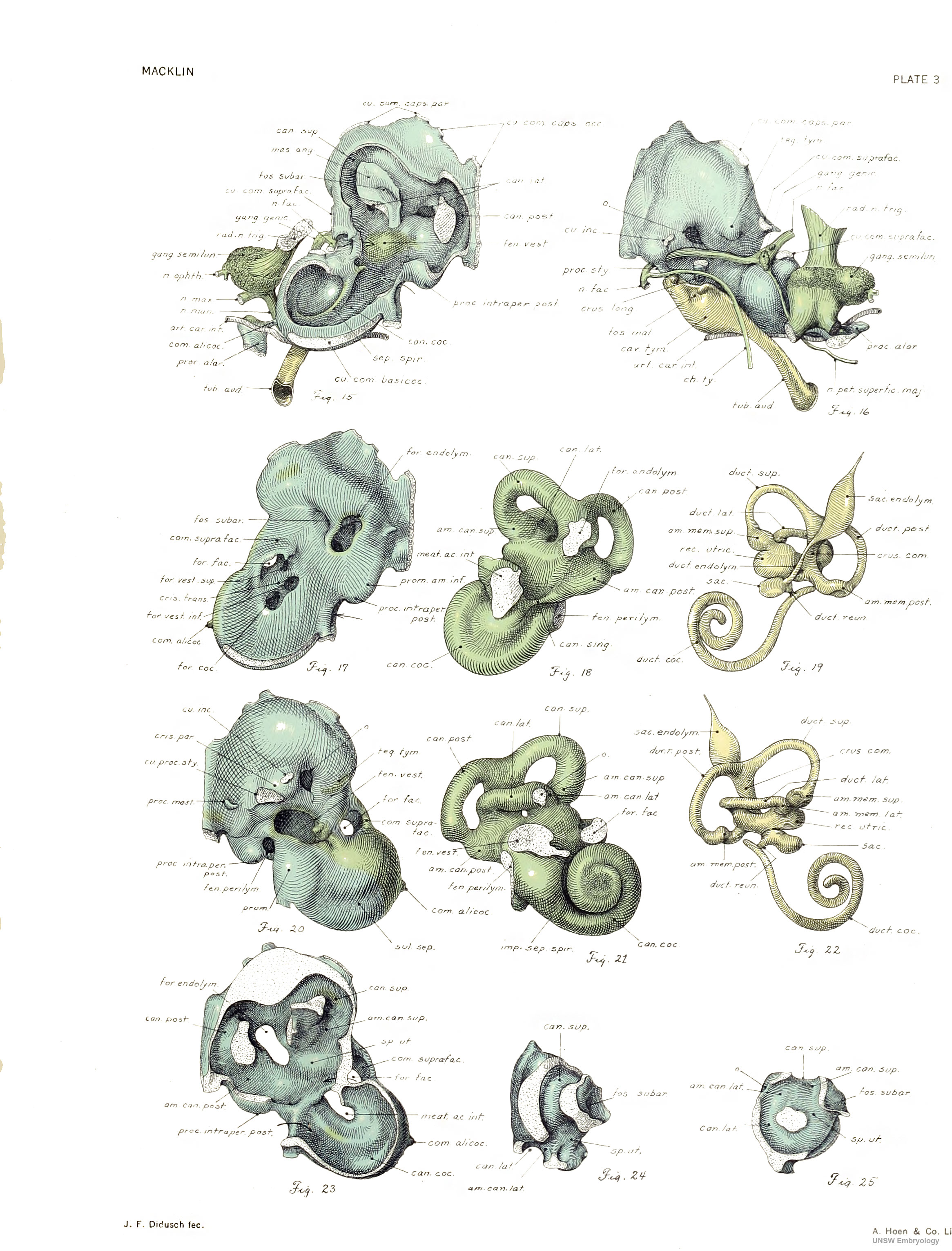 | 2,331 × 3,061 (1,012 KB) | Z8600021 (talk | contribs) | ||
| 10:35, 16 February 2011 |  | 846 × 1,113 (165 KB) | S8600021 (talk | contribs) | ==Plate 3. The skull of a human fetus of 43 millimeters greatest length== By Charles C. Macklin. (5 plates containing 47 figures) All drawings were made by Mr. James F. Didusch according to geometric projection. With the exception of figure 7, which was |
You cannot overwrite this file.
File usage
The following 3 pages use this file: